Introduction
The objective of this article is to coalesce the information published by many of the predominant sources on systems engineering into a single point of reference. This article provides elaboration upon the processes and methods described in these sources to add clarity and context by providing:
- summary and overview of each publications structure and intent,
- connections to sources and references cited by the publications,
- connections to publications and knowledge bases published by other professional organizations,
- increased fidelity for systems engineering activities beyond that of the publications,
- examples of process applications,
- lessons learned, and
- recommended best practices.
This article is an analysis of the content provided by the cited references and assumes that the reader has authorized access to the each source. This article makes every attempt to protect the copy rights of the publisher by providing summary and interpretation while minimizing duplication of the text.
References
INCOSE Systems Engineering Handbook
INCOSE (2015). The Systems Engineering Handbook, a guide for systems lifecycle processes and activities, prepared by the International Council on Systems Engineering (INCOSE). Published by John Wiley and Sons of Hoboken, NJ, USA.
Systems and software engineering - System life cycle processes
ISO/IEC/IEEE 15288:2015 (2015). Maintained and published by the International Organization for Standardization (ISO), International Electrotechnical Council (IEC) and the Institute for Electrical and Electronic Engineering IEEE.
A Guide to the Systems Engineering Body of Knowledge (SEBoK)
BKCASE (2017) The Guide to the Systems Engineering Body of Knowledge (SEBoK) was created by the Body of Knowledge and Curriculum to Advance Systems Engineering (BKCASE) project. BKCASE is overseen by a Governing Board, consisting of the International Council on Systems Engineering (INCOSE), the Systems Engineering Research Center (SERC), and the IEEE Computer Society.
Retrieved from http://sebokwiki.org/wiki/Guide_to_the_Systems_Engineering_Body_of_Knowledge_(SEBoK)
A Guide to the Project Management Body of Knowledge
PMI (2017) A Guide to the Project Management Body of Knowledge (PMBOK® Guide) 6th Edition Project Management Institute, Inc. Newtown Square, PA, USA.
Approach
Model Based Systems Engineering (MBSE) is used to collect, visualize and analyze the content within the cited references. MBSE follows the same lifecycle as conventional systems engineering, with models being the principle method of presenting the details associated with the system of interest (SOI). The SOI in this case is the Systems Life Cycle Processes and Activities as described by 15288: 2015 and the INCOSE Systems Engineering Handbook (INCOSE 2015). This article uses the following methods:
- Provide a high level summary of the process as depicted by the sources
- Created models that codify the text provided
- Performed SE analysis of the models to identify opportunities for clarification or additional details
- Revised the models to reflect the aggregate information
- Identified the areas that may align with Knowledge Bases published by other Communities of Practice
Please see Model Based Systems Engineering for more information.
Systems Life Cycle
Before investigating systems engineering processes, it is important to first discuss the lifecycle in which the processes are executed. One may ask, what is a system lifecycle? Think of the natural progression of any man made object. The lifecycle starts with the identification of a need for something. The need to eat, drink, stay warm and dry, or processes enormous amounts of data. In all cases it is important to frame the need and the aspects of a solution up front. For example:
- The food or drink must be safe to consume and it must nourish the body.
- The structure that provides warmth must house 12 people and provide protection from werewolves.
- The data solution must track and categorize all information about the unicorn collection.
In this phase of the life cycle the goal is to understand and agree upon the problem and the high level attributes of the solution.
Next with the help of an expert, the person in need begins to clarify and further describe the problem and the elements of a solution. Through analysis it may be determined:
- that the only way to keep the water safe is to mix it with a preservative,
- protein such as meat is essential for human growth,
- the minimum structure to keep out werewolves is one constructed of stone or masonry, or
- the data about the unicorn collection includes 8000 different unicorns and each unicorn may have 13 characteristics that describe the individual unicorn.
The objective of this phase in the life cycle to translate the problem or need into enough information (functional requirements) to begin to evaluate acceptable solutions.
During the next phase, the project team begins to describe the solution in terms of being feasible and acceptable. Feasible solutions are ones that are obtainable, affordable, usable, maintainable and can be disposed of when no longer usable. For example:
- In the past brewing, fermentation or distillation were the best available means to provide a safe beverage. However, over time it was determined that drinking alcohol all day might impact productivity of the consumer.
- A family could grow enough crops and raise enough livestock to sustain the family. But this model does not scale well when the population explodes and people are needed to do things other than farming.
- The database that stores the unicorn collection can be built upon a spread sheet, a stand alone data base or a web based solution. But the spread sheet would not be usable beyond a small group of users and configuration management may be a challenge.
The goal of this phase is to clarify the need (functional requirements) to enough detail to begin identifying the types of solutions that may work and then narrow down the options for the solution.
With a clear definition of the problem and feasible conceptual solution identified, the team can now begin to design the new water supply, werewolf survival house or unicorn collectors website. During this phase the functional requirements are further analyzed and decomposed into requirements that describe the new system (system requirements). Also identified are supplemental (technical) requirements that describe the things required to make the system affordable, maintainable, safe and environmentally friendly. The goal of this phase is to create a design that has enough detail that the solution can be built, used and maintained.
In most cases the development phase of the project involves the creation of individual components in several places and then integration of the solution at either the end user location or first off site before being delivered. Today, milled lumber, quarried stone and fixtures from all over the world are integrated into a building onsite or modules in a manufacturing facility before delivery to the building site. Software intensive systems are also developed in modules that are connected together as a single software application and then loaded onto a computing environment. Throughout this phase, designs are refined based on the results of recursive testing of the components as they mature. The objective of this phase is to design, develop, integrate and deliver a working solution to the end user.
One may think that the systems engineering roll in the lifecycle ends after the solution is delivered. Many organizations have made this mistake. Remember that a factor in feasibility is that it be usable, maintainable and disposable. Throughout the previous phases of the life cycle engineers should design usability and maintainability into the solution. Materials should be selected that are durable but will not harm the users or the environment. This later factor has become increasingly important as we have learned of the negative impacts that some materials have on the environment when disposed in landfills. Additionally, problems my emerge with the solution after delivery to the end user and the systems engineering team must participate in the corrective actions. Even during the disposal of the solution engineers may be involved in the safe dismantling and disposal of the components.
The phases of the systems life cycle does have a natural progression in the development of the system. But it is important to recognize that phases are often revisited as required to achieve a final working solution. Also the same lifecycle or phases of the lifecycle are followed whenever changes are made to the system.
There are many systems life cycles in existence and there are entire books on the cycle. However, the variants of the lifecycle do not change the phases or the objectives, they change the number of recursions or the timing of the phases. All start with a problem statement and end with a working solution that eventual reaches its end of life. Regardless of the life cycle model followed, the systems engineering processes described in the INCOSE Handbook are applied by the systems engineering team. What changes is how, what and when the processes are applied.
Refer to the SEBoK "Introduction to System Life Cycles" page for more information.
INCOSE Handbook Structure and Methods
INCOSE adopts and expands upon the systems engineering processes described in ISO/IEC/IEEE 15288. INCOSE does not define new processes, rather it provides amplifying information on the application of the processes defined in 15288 (INCOSE 2015). Figure 1.1 is adopted from INCOSE 2015 which itself is adopted from (ISO/IEC/IEEE 15288).
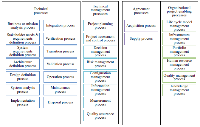
CABOKtip: The 15288 Agreement Process area is similar to the PMBOK Project Procurement Management Knowledge Area which includes the process areas: Plan Procurement Management, Conducting Procurement and Controlling Procurement knowledge areas within the PMI Project Management Body of Knowledge (PMBoK) (PMI 2017).
CABOKtip: The Organizational Process Area area is analogous to the Organizational Process Assets within the PMBoK (PMI 2017).
The INCOSE SE Handbook uses Function models to depict each process along with its inputs, outputs, mechanisms and constraints. The models are consistent with IDEF0 Activity Diagrams and Input/Process/Output (IPO) Models often used in process improvement and leaning methods. This diagramming approach is an effective way of visualizing a process from the top level. Figure 1.2 represents the Input, Process, Output Model structure used by INCOSE to introduce each process in the handbook (INCOSE 2015).
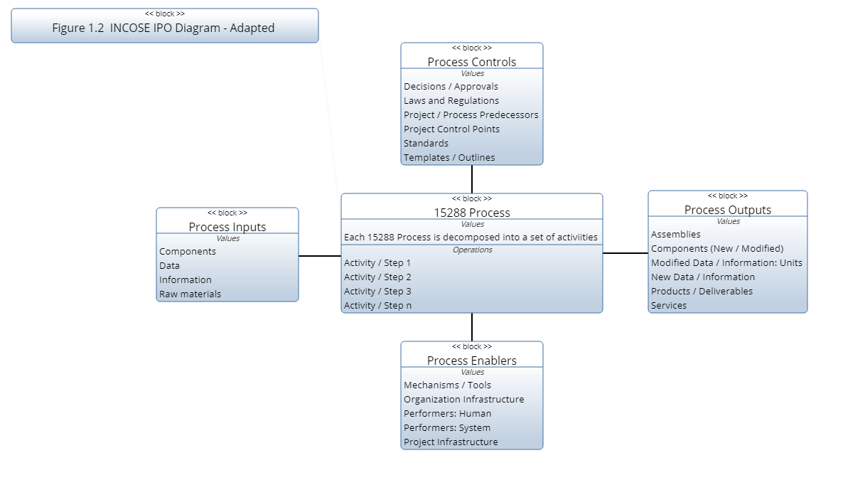
The block in the center of the diagram represents and activity or function performed in a process. Each activity / function can have one or more Inputs, Outputs, Mechanisms and Constraints.
Inputs are items that are modified or consumed by the activity / function. (Raw material, components, assemblies, data or information)
Outputs are items resulting from the activity / function: new components, assemblies, data or information. Inputs do not normally pass through an activity without being modified.
Controls are items that influence or direct how the activity is to be performed. These directions may be in the form of specifications for developing the outputs, or regulations governing the process. Regulations include safety considerations or environmental policy and design specifications define the structure or characteristics of the output.
CABOKtip: Please refer to Activity / Function Models for more information.
Technical Processes
The technical processes of 15288: 2015 describe the activities directly associated with the definition, design, development, delivery and support of the system. Each process plays a role in the end to end life cycle of a system. Remember that a SE team should apply all of theses processes in the development of a systems solution regardless of the problem or the solution. What changes from project to project is the level of effort and complexity of engineering data created for the project. The hierarchy model in Figure 1.3 represents the processes depicted in Figure 1.1. Entering all of the processes into a MBSE tool transforms the static diagram in Figure 1.1 into the data represented in Figure 1.3. The value of this step will become more evident as we progress through this article.
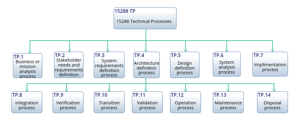
INCOSE 2015 provides the ISO/IEC/IEEE 15288 definition of each of the processes depicted in Figure 1.3 along with supplemental information provided by the Handbooks authors.
Read more about each of the Technical Processes
Technical Management Processes
Read more about each of the Technical Management Processes
Agreement Processes
Read more about each of the Agreement Processes
Organization Project Enabling Processes
Read more about each of the Organization Project Enabling Processes